From: Whip Net
Area 51 is a household term describing a breeding ground for conspiracy and top secret cover ups. Although officially, our government denies its very existence, Area 51 has become part of our popular culture, inspiring books, films and TV shows. But to truly understand the Area 51 mystique, we must look beyond the extraordinary claims and conspiracy theories.
Yucca flats, Nevada also known as Survival City, was a testing ground for the U.S. Atomic Energy Commission in a time when our country was under the paranoia of the cold war. This was a time when Area 51 was literally carved out of the Nevada desert as one of several areas set aside for atomic testing. Now known as the Department of Energy (DOE), the Atomic Energy commission grabbed the land now occupied by Groom Lake, and Area 51 airbase in the early 1950’s for nuclear weapons testing. At the time, south central Nevada was uncontested land, a place that no one cared about much at all. The land was mapped out and divided up into big boxes and the grids were named starting with Area 1. The dry, alkaline lake bed, Groom Lake was in a location labeled Area 51; while the maps are no longer used, the name Area 51 stuck and is still known by that name today.
Ariel view of Area 51
In the spring of 1955, the area in grid # 51 took on a much larger role in our government’s dealings with the Soviet Empire. Lockheed Aeronautics Engineering Genius Kelly Johnson designed America’s first super secret spy plane that year, the U2. A place was needed to test the new covert creation and spoke with a trusted friend, civilian test pilot, and the man considered by some as the true father of Area 51, Tony LeVier. Tony LeVier searched for the perfect dry lake as he knew that dry lakes were the best natural landing fields ever devised for experimental flying. LeVier knew that Groom Lake was a 10 plus and was the perfect location. The CIA was working at a facility some 40 miles away, and as they had all the necessary equipment and agreement was made for them to build the base. America’s most Top Secret facility, Area 51 was born and a few weeks later, the U2 spy plane was undergoing flight testing.
The U2 spy plane became Americas #1 resource for gaining information about the Soviet Union. Built for the CIA, the U2 was built by Lockheed Martin and capable of producing high quality, aerial images of enemy installations from as high as 80,000 feet. Although the U2 was actually a spy plane, a cover story was disseminated that it was being tested at Groom Lake for high altitude weather research for the National Advisory Committee on Aeronautics; a predecessor to NASA.
U2 Spyplane, U2
The aircraft were even painted with false NACA markings in the event that one should crash offsite. The U2 flew dozens of clandestine missions with total anonymity over several years bringing back vital photographic proof regarding Russia’s nuclear weapons buildup. In May of 1960, a U2 spy plane piloted by Francis Gary Powers was shot down over Russia and was part of a showcase trial.
The crash occurred about 5 days prior to a summit meeting coming between Eisenhower and Khrushchev, a very sensitive moment in time. Powers was convicted of spying by a Soviet court and sentenced to 10 years in prison but he was later released in exchange for a soviet agent in US custody. The intelligence gained by the U2 efforts is credited as saving the US from World War III. After the U2 project was completed, Groom Lake was used for testing the A12 spy plane which was built for flying above 80,000 feet in excess of Mach 3. The A12 is the predecessor to the SR71 Blackbird, which is still flying today and used for high altitude military reconnaissance.
As enemy technology advanced, and even our most sophisticated aircraft became vulnerable, the clandestine projects at Area 51 took on an urgent and surprisingly new direction. A new kind of aircraft was being tested in the dark skies above Area 51. Reportedly, various American agents were able to gain access to various Russian aircraft and radar technology and the hardware was taken to Area 51. Backwards engineering of Russian technology was not the only major secret being contained at Groom Lake.
In the 70’s, the era of Stealth began with what were known as “Blue planes”. Also known as technology demonstrators were being built and flown. Another program known as “Tacid Blue” blue projects which gave rise to Americas most top secret aircraft to date. For years, there were reports of strange black wedges piercing the skies above Groom Lake, along with rumors of stealth aircraft, decades ahead of its time.
F117, Stealth aircraft
For once, it seemed that rumors about Area 51 were more factual than fictional when in 1988, the US government unveiled the B2 stealth bomber and the F117 stealth fighter. The stealth program held true to the idea that keeping new technology a secret as long as possible will help to keep the enemy from getting an advantage over that technology. During the testing of the F117, everything involved working at night. Everyone involved adapted to living and working at night, even the pilots dressed all in black. The secrets of Area 51 continue with the development of the alleged, high tech aircraft known as the Aurora. Based on revolutionary technology, this aircraft is said to fly at 6 times the speed of sound, and can attack with pinpoint accuracy. Area 51 would be the perfect place to build and test such an aircraft as it would require a large tract of land and big base to support it. The US Government insists that such an aircraft does not exist at this time, but indeed would be very nice to have in its arsenal.
In 1996, the state of Nevada officially dubbed route 375 as the Extraterrestrial highway due to the countless sightings of UFO’s by residents and visitors to the area. The whole UFO and alien connection can be traced directly to MIT graduate and physicist Bob Lazar. Bob Lazar went public in 1989 with a claim that he been involved in a project to backwards engineer a captured alien spacecraft. The media went wild his story about working at an area known as S4, which was built into the side of a mountain launching the continuing stories that aliens and alien spacecraft are being held and tested at the airbase. The nearby town of Rachael Nevada has transformed into a Mecca for believers and non believers alike. The little Alieinn has become a hot spot for visitors to trade stories and theories about UFO’s and aliens alike.
In August, 1997, the CIA released a report that the thousands of UFO sightings since the 1940’s was used by the government to cover up actual military testing. Many believe that the report is more disinformation in order to get people to think that there was nothing to the UFO story and stop investigating such stories. Area 51 is a very hostile region ringed by mountains unbearable heat and the far reaching security forces. The border around the base is not fenced, and is poorly marked, but it is laced with sensors, cameras and other electronic media for tracking all visitors.
tikaboo peak
The area around the base, even public land so advanced that the even odors of any visitor can be detected and determined to be human, animal, or other. The government is very protective about whatever is going on at Area 51, any encroachment upon the area is met with extreme prejudice and brute force; this without ever having reached the most remote guard shack. Area 51 has recently increased security in an ever expanding perimeter. There are 2 mountains where onlookers could view the airbase until the Air Force was granted a 4000 acre increase into the restricted area. The two mountains, Freedom ridge, the other is Whitesides Mountain which are 11 and 12 miles away, respectively, The next nearest mountain is 26 miles away to Tikaboo peak if you want to see Area 51.
After 40 years of denial that the base actually existed, the US government actually acknowledged the existence of Area 51. Clinton’s Area 51 Exemption, officially, Presidential Determination No. 95-45 served only to increase the secrecy around Area 51. The document was originally scheduled to require annual renewal, and gave the agency the prerogative to not answer certain questions regarding the base.
Tuesday, August 31, 2010
Wednesday, August 4, 2010
Failure Analysis Of Mishap At DMRC On 12 July
It was 12th July 2009 which proved to be the darkest day in the history of DMRC. After achieving a milestone of providing a reliable and easy mean of transportation to the capital of India, it is now facing huge problems which are not only causing loss of human lives but also causing immense damage to the most reputed infrastructure organization of India. So far, this company has achieved every target ahead of schedule under the excellent guidance of Mr. Sreedharan.
Let us try understanding what went wrong on that disastrous day
On 12th July, 2009, while lifting segments of the superstructure, an accident happened in the Badarpur – Secretariat section near P-67. The pier cap of pier P-67 got collapsed causing subsequent collapse of the
(i) Launching Girder
(ii) Span between P-66 and P-67 which had got erected and pre-stressed, already
(iii) Segments of the superstructure for the span between P-67 and P-68.
The incident left 6 people dead and many injured.
Site Investigation
After visiting the site, following observations were noticed
1. The pier cap of affected pier (P-67) has sheared from the connection point of the pier and pier
cap. It is a cantilever pier cap. It was informed by the contractor and DMRC representatives that the support system for viaductwas initially designed as portal pier till the casting of the pier was over. The shop owners put up resistance against casting of the other leg of the portal and it was subsequently decided by DMRC that this would be changed to a cantilever pier, similar to P-68 which is still standing at site.
metro collapse Pier fall
2. It was noticed that the prop support of the cantilever has failed from its connection to the pier.
3. The top reinforcement of the cantilever beam does not have any development length into pier
concrete. As learned from the sources, the top reinforcement of the cantilever beam had an “L”
bend of 500 mm only.
p67-p68fall
There is very nominal (or no trace) of shear reinforcement at the juncture.
4. The launching girder has fallen below with the failure of pier cap. Also, the span between P-67
and P-68 has fallen inclined, supported by the ground at one end and pier cap (P-68) on the
other.
top-reinforcement
5. The boom of the crane, used for lifting the launching girder on 13 July, 2009, has failed in bending
and shows clear sign of overloading.
overloaded-crane-crash
Analysis
i. The pier (P-67) was initially designed as a leg of a portal frame and subsequently changed to support cantilever pier cap.
ii. The same method was followed for P-68 and P-66.
iii. The alignment of track here is in curvature and gradually leaves the median of the road to align on one side of the road.
iv. The longitudinal reinforcement of the pier was protruding by around 1500 mm beyond top of pier.
v. The top reinforcement of pier cap was 36 mm in diameter and had a development length of 500 mm. only as an “L” from the top. There was insufficient bond length for the structure to behave like a cantilever beam.
vi. During launching operation of the launching girder itself, this pier cap developed crack and work was stopped for couple of months. During this period, the cantilever pier cap was grouted in crack areas and further strengthened by introducing prop or jacketing.
vii. However, the behavior of the structure changed due to introduction of this jacket and the cantilever pier cap remained no more cantilever.
viii. The segments of superstructure for the span between P-66 and P-67 was erected and launched and the prop beam / jacketing could sustain the load to that extend.
ix. During the launching of superstructure segments between P-67 and P-68, only 6 segments could be lifted and the whole system collapsed when seventh segment was hooked for lifting.
The sequence of failure is as follows:
a. The support of the prop / jacket got sheared from its connection due to inadequate section / welding.
b. The cantilever pier cap which was behaving as a simply supported beam due to introduction of prop / jacket started behaving like a cantilever beam suddenly after failure of the prop which it can not sustain ( It was inadequately designed). So, the so called “cantilever pier cap” collapsed.
c. The launching girder / span between P-67 & P-66 / the temporarily erected segments between P-67 and P-68, all got collapsed in one go.
Crane Failure
The launching girder was lifted by the cranes. However, it needed to be pushed little forward for
unloading it on the ground. So, all the cranes were asked to stretch there booms by some length.
During this operation, the 250 MT capacity crane on extreme left exceeded it’s capacity and the
boom failed and broke down. Since, there were unequal loading on the 250 MT crane by it’s side,
that also failed and broke down. The crane of 350 MT capacity didn’t broke but it toppled with it’s
base. The 400 MT crane remained intact.
Final overview
a. It is concluded that the failure of pier cap occurred due to inadequate prop / jacket. This was coupled with failure of cantilever pier cap due to inadequate development length of top reinforcement of the cantilever pier cap.
b. The failure of the crane was a case of operational inexperience for such synchronized crane operation. The crane -1 did not have the requisite capacity for the extended boom length and radius. Once crane – 1 failed, the crane – 2 was loaded almost half of the launching girder amounting to around 200 MT. For the extension of boom and radius, it did not have the requisite capacity so it failed, too. The crane -3 was loaded more than it’s capacity. However, in this case the crane got toppled instead of boom getting sheared. The crane -4 did not undergo the severe loading due to failure of other 3 cranes and most of the loads got grounded by that time.
What it taught us?
a. Structural designs should be proof checked by experienced structural engineer.
b. Once failure observed, structure should be as far as practicable abandoned and new structure should be built up
c. More emphasis should be given on detailing of reinforcement to cater for connections and behavior of the structural components.
d. Any make-shift arrangement to save a failed structure should be avoided.
e. Reinforcement detailing in corbels, deep beams, cantilever structures should be checked as per the provisions of more than one type of Standards (both IS & BS should be followed).
f. Adequately experienced Engineer / Forman should be deployed for erection works.
This article has been written/submitted to us by a Civil Engineer and we are thankful to him/her for his so valuable inputs.
Filed under Civil Engineering Disasters
Monday, August 2, 2010
What happen in Chernobyl?
On April 26, 1986 nuclear engineer Cliff Robinson's radiation detector went off as he tried to enter his office at the Chernobyl Nuclear Power Plant. He checked the radiation levels of a shoe and could not believe his eyes. Readings had soared and there were signs of radioactive substances never seen before. "My first thought was that a war had broken out and that somebody had blown up a nuclear bomb".

The reactor had an imperfection of control and protection system that made the reactor very unstable. In addition, safety operation rules were violated when the reactor protection system was switched off. This allowed for the disaster to be much more destructive. The second electroturbogenerator was then turned off. This led to a practically instantaneous catastrophic increase of thermal power. As a result, a steam explosion occurred; the reactor and a part of the building were destroyed. Radioactive materials accumulated in the reactor core started to be thrown out into the environment. Multiple fire sites formed both inside the reactor hall and on roofs of nearby buildings because of the explosion. Fire officials smothered main fire sites, except the central reactor hall where graphite continued to burn in the close vicinity of the destroyed reactor. In subsequent days, about 5000 tons of materials, including about 40 tons of substances containing boron and absorbing neutrons, 2400 tons of lead, 1800 tons of sand and clay, 600 tons of dolomite, trinatriumphosphate and polymerizing liquids were thrown into the reactor well from helicopters of air forces to extinguish burning graphite and suppress radioactive release.
By 5 o'clock on April 26, 1986 the fire officials smothered main fire sites except the central reactor hall, where graphite continued to burn in the close vicinity of the destroyed reactor. Contrary to existing reports new reports concluded that the helicopter airlifts of 5,000 tons of clay and other materials to smother the smoldering reactor core was unsuccessful. The pilots of the over 1,800 helicopter missions were told to aim for a "red glow" in the reactor building, which Soviet officials believed to be the burning core. According to the reports, the pilots hit the wrong target. The reports indicated that the core was actually located about 50 feet from the glow. The source of the glow remains uncertain. However, it could have been a small chunk of burning reactor material ejected during the initial explosion. Because the core was never smothered, the reactor continued to burn for 10 days before it was finally extinguished. The core underwent what experts consider the worst-case scenario a complete - core meltdown. Nine days after the accident, the liquefied core melted through the 6-foot radiation shield of the reactor chamber and spilled out into the concrete floors of the level beneath. There the material spread out enough to end the nuclear reaction.

The reactor emitted between 185 and 250 million curies of radiation because the core was not shielded immediately. These levels are three to five times as high as the 50 million curies reported in the official Russian account. In comparison, one curie is the amount of radiation given off by one gram of radium. In addition, the large amount of radiation seems to be linked to a higher incidence of thyroid cancer among children in Ukraine and nearby Belarus. One of the most pervasive myths about Chernobyl is that only 3% of the reactor core were released into the biosphere when the explosion occurred on April 26, 1986. Vladimir Chernousenko, Scientific Director of the Ukrainian Academy of Sciences' Task Force for the Rectification of the Consequences of the Accident, in his 1991 book Chernobyl, Insight From the Inside, dispels this myth (and a partial list of 20 others), citing a more official view on `The Nuclear Accident in Block 4 of the Chernobyl Nuclear Power Station and the Safety of the RBMK Reactor' gives the following excerpts from an unpublished report by A.A. Yadrikhinskii, Nuclear Safety Inspection Engineer of the USSR State Atomic Energy Survey Commission (Kurchatov town, RSFSR February, 1988):
"Radiation emission was no less that 80% of the core (with a total of 192 tons), which amounted to 6.4 x 10^9 Ci. Choosing to ignore the facts about how we are collectively contaminating this Earth with lethal-to-all-life-doses of man-made nuclear fission products will ensure the cessation of billions of years of life exploring itself on this planet. It doesn't have to go down this way. If we were living in the areas that the children described below are, we would not be able to ignore the facts which the International Nuclear Mafia continuously deny when they parrot the line in the global media about how "There's no health danger from nuclear power" and "No one died at Chernobyl" and "This form of energy is clean and safe; anyone who says otherwise doesn't know what they're talking about".

The incident took a brutal toll on the community. Thirty people (staff of block and fire brigade) died receiving high doses of radiation. The contaminated area has been measured to be more than 130,000 sq. km. Approximately 4.9 millions people lived on this territory before the accident. All population from 30-km zone was evacuated. A number of people were relocated. Impact of the Chernobyl Accident on the Nuclear Energy Policy is tremendous. Some countries stopped national nuclear energy programs all together. Constructions of new plants in USSR were frozen. Globally, public opinion was directed against nuclear power plants. Some plants were closed. The Chernobyl accident had initiated an international activity in the area of nuclear safety and nuclear emergency planning.


Genetic Engineering Gives Multinationals Power over Food, Crops & Farmers

Genetic engineering is giving the multinationals power over food, crops and farmers. It is largely untested. The aim is so that the multinationals can make profits instead of benefiting the needy. Patents on the technology make it illegal (or impossible due to sterilization) for farmers to save, replant or share GMO's seeds. Before every harvest, the farmer will therefore have to buy seed from the multinationals. Genetically engineered crops could destroy organic ones, due to cross-pollination. This could also harm native species and create super-weeds. Organics are becoming more popular. Many foods don't indicate that they contain genetic contents on the label. Despite imposing an environmental and health risk, multinationals are increasing the use of GMO's. The Green Revolution of the 60's was only about crossing related species, which is often natural. The problem is not the lack of good food in the world; it is the corruption affecting the distribution system. As well as those who are corrupt, there are many honest victims starving. (46) For best results the Green Revolution relied on expensive fertilizers, chemicals and machinery that were cheaper for the larger farms that bought in bulk. It was often not economical for the smaller ones who had to pay higher costs and interest and receive fewer subsidies. People either had to expand into super farms or get out of the industry in order to remain profitable. Lower profits per unit did not affect larger farms, which had greater turnover and capital. They did not have to be as efficient as smaller farms to survive, and they had more influence over government policy. As fertilizer was increased, the production per ton of fertilizer fell. Increasing amounts of fertilizers were needed to prevent soil nutrient decline. More pesticides were needed to overcome resistance. This degraded the land and damaged the environment so in many cases the long term yields fell after peaking. Apart from China where there was a dramatic fall, the number of hungry people increased during the Green Revolution. It may have been the Chinese revolution and not the Green Revolution that made the difference. Small farms went bankrupt, people moved into the cities, unemployment increased, food distribution became more uneven and poverty increased. Large farms made large profits and often linked with or became multinational companies. (46.2)
Sunday, August 1, 2010
Taking Lessons From What Went Wrong
By WILLIAM J. BROAD
Published: July 19, 2010

Published: July 19, 2010
Disasters teach more than successes.
Associated Press
COLLAPSE The Tacoma-Narrows Bridge plunged into Puget Sound on Nov. 11, 1940, in winds of 40 miles per hour. There were no human fatalities.
While that idea may sound paradoxical, it is widely accepted among engineers. They say grim lessons arise because the reasons for triumph in matters of technology are often arbitrary and invisible, whereas the cause of a particular failure can frequently be uncovered, documented and reworked to make improvements.
Disaster, in short, can become a spur to innovation.
There is no question that the trial-and-error process of building machines and industries has, over the centuries, resulted in the loss of much blood and many thousands of lives. It is not that failure is desirable, or that anyone hopes for or aims for a disaster. But failures, sometimes appalling, are inevitable, and given this fact, engineers say it pays to make good use of them to prevent future mistakes.
The result is that the technological feats that define the modern world are sometimes the result of events that some might wish to forget.
“It’s a great source of knowledge — and humbling, too — sometimes that’s necessary,” said Henry Petroski, a historian of engineering at Duke University and author of “Success Through Failure,” a 2006 book. “Nobody wants failures. But you also don’t want to let a good crisis go to waste.”
Now, experts say, that kind of analysis will probably improve the complex gear and procedures that companies use to drill for oil in increasingly deep waters. They say the catastrophic failure involving the Deepwater Horizon oil rig in the Gulf of Mexico on April 20 — which took 11 lives and started the worst offshore oil spill in United States history — will drive the technological progress.
“The industry knows it can’t have that happen again,” said David W. Fowler, a professor at the University of Texas, Austin, who teaches a course on forensic engineering. “It’s going to make sure history doesn’t repeat itself.”
One possible lesson of the disaster is the importance of improving blowout preventers — the devices atop wells that cut off gushing oil in emergencies. The preventer on the runaway well failed. Even before the disaster, the operators of many gulf rigs had switched to more advanced preventers, strengthening this last line of defense.
Of course, an alternative to improving a particular form of technology might be to discard it altogether as too risky or too damaging.
Abandoning offshore drilling is certainly one result that some environmentalists would push for — and not only because of potential disasters like the one in the gulf. They would rather see technologies that pump carbon into the atmosphere, threatening to speed global climate change, go extinct than evolve.
In London on June 22 at the World National Oil Companies Congress, protesters from Greenpeace interrupted an official from BP, the company that dug the runaway well. Planetary responsibility, a protestor shouted before being taken away, “means stopping the push for dangerous drilling in deep waters.”
The history of technology suggests that such an end is unlikely. Devices fall out of favor, but seldom if ever get abolished by design. The explosion of the Hindenburg showed the dangers of hydrogen as a lifting gas and resulted in new emphasis on helium, which is not flammable, rather than ending the reign of rigid airships. And engineering, by definition, is a problem-solving profession. Technology analysts say that constructive impulse, and its probable result for deep ocean drilling, is that innovation through failure analysis will make the wells safer, whatever the merits of reducing human reliance on oil. They hold that the BP disaster, like countless others, will ultimately inspire technological advance.
The sinking of the Titanic, the meltdown of the Chernobyl reactor in 1986, the collapse of the World Trade Center — all forced engineers to address what came to be seen as deadly flaws.
“Any engineering failure has a lot of lessons,” said Gary Halada, a professor at the State University of New York at Stony Brook who teaches a course called “Learning from Disaster.”
Design engineers say that, too frequently, the nature of their profession is to fly blind.
Eric H. Brown, a British engineer who developed aircraft during World War II and afterward taught at Imperial College London, candidly described the predicament. In a 1967 book, he called structural engineering “the art of molding materials we do not really understand into shapes we cannot really analyze, so as to withstand forces we cannot really assess, in such a way that the public does not really suspect.”
Among other things, Dr. Brown taught failure analysis.
Dr. Petroski, at Duke, writing in “Success Through Failure,” noted the innovative corollary. Failures, he said, “always teach us more than the successes about the design of things. And thus the failures often lead to redesigns — to new, improved things.”
One of his favorite examples is the 1940 collapse of the Tacoma Narrows Bridge. The span, at the time the world’s third-longest suspension bridge, crossed a strait of Puget Sound near Tacoma, Wash. A few months after its opening, high winds caused the bridge to fail in a roar of twisted metal and shattered concrete. No one died. The only fatality was a black cocker spaniel named Tubby.
Dr. Petroski said the basic problem lay in false confidence. Over the decades, engineers had built increasingly long suspension bridges, with each new design more ambitious.
The longest span of the Brooklyn Bridge, which opened to traffic in 1883, was 1,595 feet. The George Washington Bridge (1931) more than doubled that distance to 3,500 feet. And the Golden Gate Bridge (1937) went even farther, stretching its middle span to 4,200 feet.
“This is where success leads to failure,” Dr. Petroski said in an interview. “You’ve got all these things working. We want to make them longer and more slender.”
The Tacoma bridge not only possessed a very long central span — 2,800 feet — but its concrete roadway consisted of just two lanes and its deck was quite shallow. The wind that day caused the insubstantial thoroughfare to undulate wildly up and down and then disintegrate. (A 16-millimeter movie camera captured the violent collapse.)
Teams of investigators studied the collapse carefully, and designers of suspension bridges took away several lessons. The main one was to make sure the road’s weight and girth were sufficient to avoid risky perturbations from high winds.
Dr. Petroski said the collapse had a direct impact on the design of the Verrazano-Narrows Bridge, which opened in 1964 to link Brooklyn and Staten Island. Its longest span was 4,260 feet — making it, at the time, the world’s longest suspension bridge and potentially a disaster-in-waiting.
To defuse the threat of high winds, the designers from the start made the roadway quite stiff and added a second deck, even though the volume of traffic was insufficient at first to warrant the lower one. The lower deck remained closed to traffic for five years, opening in 1969.
“Tacoma Narrows changed the way that suspension bridges were built,” Dr. Petroski said. “Before it happened, bridge designers didn’t take the wind seriously.”
Another example in learning from disaster centers on an oil drilling rig called Ocean Ranger. In 1982, the rig, the world’s largest, capsized and sank off Newfoundland in a fierce winter storm, killing all 84 crew members. The calamity is detailed in a 2001 book, “Inviting Disaster: Lessons from the Edge of Technology,” by James R. Chiles.
The floating rig, longer than a football field and 15 stories high, had eight hollow legs. At the bottom were giant pontoons that crewmen could fill with seawater or pump dry, raising the rig above the largest storm waves — in theory, at least.
The night the rig capsized, the sea smashed in a glass porthole in the pontoon control room, soaking its electrical panel. Investigators found that the resulting short circuits began a cascade of failures and miscalculations that resulted in the rig’s sinking.
The lessons of the tragedy included remembering to shut watertight storm hatches over glass windows, buying all crew members insulated survival suits (about $450 each at the time) and rethinking aspects of rig architecture.
“It was a terrible design,” said Dr. Halada of the State University of New York. “But they learned from it.”
Increasingly, such tragedies get studied, and not just at Stony Brook. The Stanford University Center for Professional Development offers a graduate certificate in advanced structures and failure analysis. Drexel University offers a master’s degree in forensic science with a focus on engineering.
So too, professional engineering has produced a subspecialty that investigates disasters. One of the biggest names in the business is Exponent, a consulting company based in Menlo Park, Calif. It has a staff of 900 specialists around the globe with training in 90 engineering and scientific fields.
Exponent says its analysts deal with everything from cars and roller coasters to oil rigs and hip replacements. “We analyze failures and accidents,” the company says, “to determine their causes and to understand how to prevent them.”
Forensic engineers say it is too soon to know what happened with Deepwater Horizon, whose demise flooded the gulf with crude oil. They note that numerous federal agencies are involved in a series of detailed investigations, and that President Obama has appointed a blue-ribbon commission to make recommendations on how to strengthen federal oversight of oil rigs.
But the engineers hold, seemingly with one voice, that the investigatory findings will eventually improve the art of drilling for oil in deep waters — at least until the next unexpected tragedy, and the next lesson in making the technology safer.
One lesson might be to build blowout preventers with more than one blind shear ram. In an emergency, the massive blades of these devices slice through the drill pipe to cut off the flow of gushing oil. The Deepwater Horizon had just one, while a third of the rigs in the gulf now have two.
Perhaps regulators will decided that rig operators, whatever the cost, should install more blind shear rams on all blowout preventers.
“It’s like our personal lives,” said Dr. Fowler of the University of Texas. “Failure can force us to make hard decisions.”
The Royal Mail Ship Titanic: Did a Metallurgical Failure Cause a Night to Remember?
A metallurgical analysis of steel taken from the hull of the Titanic's wreckage reveals that it had a high ductile-brittle transition temperature, making it unsuitable for service at low temperatures; at the time of the collision, the temperature of the sea water was -2°C. The analysis also shows, however, that the steel used was probably the best plain carbon ship plate available at the time of the ship's construction.
INTRODUCTION
In the early part of this century, the only means of transportation for travelers and mail between Europe and North America was by passenger steamship. By 1907, the Cunard Steamship Company introduced the largest and fastest steamers in the North Atlantic service: the Lusitania and the Mauritania. Each had a gross tonnage of 31,000 tons and a maximum speed of 26 knots. In that year, Lord William James Pirrie, managing director and controlling chair of the Irish shipbuilding company Harland and Wolff, met with J. Bruce Ismay, managing director of the Oceanic Steam Navigation Company, better known as the White Star Line (a name taken from its pennant). During this meeting, plans were made to construct three enormous new White Star liners to compete with the Lusitania and Mauritania on the North Atlantic by establishing a three-ship weekly steamship service for passengers and mail between Southampton, England, and New York City. This decision required the construction of a trio of luxurious steamships. The first two built were the RMS Olympic and the RMS Titanic; a third ship, the RMS Britannic, was built later
The Titanic began its maiden voyage to New York just before noon on April 10, 1912, from Southampton, England. Two days later at 11:40 p.m., Greenland time, it struck an iceberg that was three to six times larger than its own mass, damaging the hull so that the six forward compartments were ruptured. The flooding of these compartments was sufficient to cause the ship to sink within two hours and 40 minutes, with a loss of more than 1,500 lives. The scope of the tragedy, coupled with a detailed historical record, have fueled endless fascination with the ship and debate over the reasons as to why it did in fact sink. A frequently cited culprit is the quality of the steel used in the ship's construction. A metallurgical analysis of hull steel recovered from the ship's wreckage provides a clearer view of the issue.
THE CONSTRUCTION
The three White Star Line steamships were 269.1 meters long, 28.2 meters maximum wide, and 18 meters tall from the water line to the boat deck (or 53 meters from the keel to the top of the funnels), with a gross weight of 46,000 tons. Because of the size of these ships, much of the Harland and Wolff shipyard in Belfast, Ireland, had to be rebuilt before construction could begin; two larger ways were built in the space originally occupied by three smaller ways. A new gantry system with a larger load-carrying capacity was designed and installed to facilitate the construction of the larger ships. The Titanic under construction at the shipyard is shown in Figure 1.
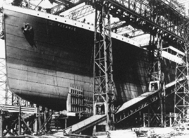 |
| Figure 1. The Titanic under construction at the Harland and Wolff shipyard in Ireland. (Photo courtesy of the Titanic Historical Society.) |
The ships were designed to provide accommodations superior to the Cunard ships, but without greater speed. The first on-board swimming pools were installed as was a gymnasium that included an electric horse and an electric camel, a squash court, a number of rowing machines, and stationary bicycles, all supervised by a staff of professional instructors. The public rooms for the first-class passengers were large and elegantly furnished with wood paneling, stained-glass windows, comfortable lounge furniture, and expensive carpets. The decor of the first class cabins, in addition to being luxurious, differed in style from cabin to cabin. As an extra feature on the Titanic, the Café Parisienne offered superb cuisine.
The designed speed for these ships was 21-22 knots, in contrast to the faster Cunard ships. To achieve this speed, each ship had three propellers; each outboard propeller was driven by a separate four-cylinder, triple expansion, reciprocating steam engine. The center propeller was driven by a low-pressure steam turbine using the exhaust steam from the two reciprocating engines. The power plant was rated at 51,000 I.H.P. To provide the necessary steam for the power plant, 29 boilers were available, fired by 159 furnaces. In addition to propelling the ship, steam was used to generate electricity for various purposes, distill fresh water, refrigerate the perishable food, cook, and heat the living space. Coal was burned as fuel at a rate of 650 tons per day when the ship was underway. Stokers moved the coal from the bunkers into the furnaces by hand. The bunkers held enough coal for a ten-day voyage.
| THE LIVES OF THE SISTER SHIPS |
|---|
| The RMS Olympic made more than 500 round trips between Southampton and New York before it was retired in 1935 and was finally broken up in 1937. In 1919, it became the first large ship to be converted from coal to oil. On May 15, 1934, as the Olympic approached New York, it struck the Nantucket light ship during a heavy fog, cutting it in half. Of the crew, four were drowned, three were fatally injured, and three were rescued. The third ship of the series, the Britannic, had a short life. While it was being constructed, the Titanic was sunk. Immediately, the design was changed to provide a double hull and the bulkheads were extended to the upper deck. Before the Britannic was completed, World War I broke out, and the vessel was converted into a hospital ship. On November 21, 1916, it was proceeding north through the Aegean Sea east of Greece when it struck a mine. Because the weather had been warm, many of the portholes had been opened, hence rapid flooding of the ship occurred. The ship sank in 50 minutes with a small loss of life; one of the loaded life boats was drawn into a rotating propeller. |
The remodeled shipyard at Harland and Wolff was large enough for the construction of two large ships simultaneously. The keel of the Olympic was laid December 16, 1908, while the Titanic's keel followed on March 31, 1909. The Olympic was launched on October 20, 1910, and the Titanic on May 31, 1911. In the early 20th century, ships were constructed using wrought-iron rivets to attach steel plates to each other or to a steel frame. The frame itself was held together by similar rivets. Holes were punched at appropriate sites in the steel-frame members and plates for the insertion of the rivets. Each rivet was heated well into the austenite temperature region, inserted in the mated holes of the respective plates or frame members, and hydraulically squeezed to fill the holes and form a head. Three million rivets were used in the construction of the ship.
The construction of the Titanic was delayed due to an accident involving the Olympic. During its fifth voyage, the Olympic collided with the British cruiser, HMS Hawke, damaging its hull near the bow on the port (left) side. This occurred in the Solent off Southampton on September 20, 1911. The Olympic was forced to return to Belfast for repairs. To accomplish the repairs in record time and to return the ship to service promptly, workmen were diverted from the Titanic to repair the Olympic.
On April 2, 1912, the Titanic left Belfast for Southampton and its sea trials in the Irish Sea. After two days at sea, the Titanic, with its crew and officers, arrived at Southampton and tied up to Ocean Dock on April 4. During the next several days, the ship was provisioned and prepared for its maiden voyage.
THE VOYAGE
On the morning of April 10, 1912, the passengers and remaining crew members came to Ocean Dock to board the ship for its maiden voyage. Shortly before noon, the Titanic cast off and narrowly avoided colliding with a docked passenger ship, the New York (which broke its mooring cables due to the surge of water as the huge ship passed), before proceeding down Southampton Water into the Solent and then into the English Channel. After a stop at Cherbourg, France, on the evening of April 10th and a second stop at Queenstown (now Cobh), Ireland, the next morning to take on more passengers and mail, the Titanic headed west on the Great Circle Route toward the Nantucket light ship 68 kilometers south of Nantucket Island off the southeast coast of Massachusetts. The Irish coast was left behind about dusk on April 11.
| Table I. A Summary of Damaged Areas in Hull by Compartment* | |
|---|---|
| Compartment | Computer Calculations (m2) |
| Fore Peak Cargo Hold 1 Cargo Hold 2 Cargo Hold 3 Boiler Room 6 Boiler Room 5 Total Area | 0.056 0.139 0.288 0.307 0.260 0.121 1.171 |
| *The compartments are listed in order from the bow toward the stern. | |
During the early afternoon of April 12, the French liner, La Touraine, sent advice by radio of ice in the steamship lanes, but this was not uncommon during an April crossing. This advice was sent nearly 60 hours before the fatal collision. As the voyage continued, the warnings of ice received by radio from other ships became more frequent. With time, these warnings gave more accurate information on the location of the icefields and it became apparent that a very large icefield lay in the ship's course. On the basis of several reports after the accident, it was estimated that the icefield was 120 km long on a northeast-southwest axis and 20 km wide; there is evidence that the Titanic was twice diverted to the south in a vain effort to avoid the fields. The ship continued at a speed of about 21.5 knots.
On the moonless night of April 14, the ocean was very calm and still. At 11:40 p.m., Greenland time, the lookouts in the crow's nest sighted an iceberg immediately ahead of the ship; the bridge was alerted. The duty officer ordered the ship hard to port and the engines reversed. In about 40 seconds, as the Titanic was beginning to respond to the change in course, it collided with an iceberg estimated to have a gross weight of 150,000-300,000 tons. The iceberg struck the Titanic near the bow on the starboard (right) side about 4 m above the keel. During the next 10 seconds, the iceberg raked the starboard side of the ship's hull for about 100 m, damaging the hull plates and popping rivets, thus opening the first six of the 16 watertight compartments formed by the transverse bulkheads. Inspection shortly after the collision by Captain Edward Smith and Thomas Andrews, a managing director and chief designer for Harland and Wolff and chief designer of the Titanic, revealed that the ship had been fatally damaged and could not survive long. At 2:20 a.m., April 15, 1912, the Titanic sank with the loss of more than 1,500 lives.
THE SINKING
Initial studies of the sinking proposed that a continuous gash in the hull 100 m in length was created by the impact with the iceberg. More recent studies indicate that discontinuous damage occurred along the 100 m length of the hull. After the sinking, Edward Wilding, design engineer for Harland and Wolff, estimated that the collision had created openings in the hull totaling 1.115 m2, based on the reports of the rate of flooding given by the survivors. This damage to the hull was sufficient to cause the ship to sink. Recent computer calculations by Hackett and Bedford using the same survivors' information, but allocating the damage individually to the first six compartments that were breached, is given in Table I. This shows a total damage area of 1.171 m2, which is a slightly larger area than the estimate by Wilding.
At the time of the accident, there was disagreement among the survivors as to whether the Titanic broke into two parts as it sank or whether it sank intact. On September 1, 1985, Robert Ballard found the Titanic in 3,700 m of water on the ocean floor. The ship had broken into two major sections, which are about 600 m apart. Between these two sections is a debris field containing broken pieces of steel hull and bulkhead plates, rivets that had been pulled out, dining room cutlery and chinaware, cabin and deck furniture, and other debris.
The only items to survive at the site are those made of metals or ceramics. All items made from organic materials have long since been consumed by scavengers, except for items made from leather such as shoes, suitcases, and mail sacks; tanning made leather unpalatable for the scavengers. The contents of the leather suitcases and mail sacks, having been protected, have been retrieved and restored. Ethical and legal issues associated with the recovery of such items are described in the sidebar authored by C.R. McGill.
| Table II. The Composition of Steels from the Titanic, a Lock Gate, and ASTM A36 Steel | |||||||||
|---|---|---|---|---|---|---|---|---|---|
| C | Mn | P | S | Si | Cu | O | N | MnS: Ratio | |
| Titanic Hull Plate | 0.21 | 0.47 | 0.045 | 0.069 | 0.017 | 0.024 | 0.013 | 0.0035 | 6.8:1 |
| Lock Gate* | 0.25 | 0.52 | 0.01 | 0.03 | 0.02 | — | 0.018 | 0.0035 | 17.3:1 |
| ASTM A36 | 0.20 | 0.55 | 0.012 | 0.037 | 0.007 | 0.01 | 0.079 | 0.0032 | 14.9:1 |
| *Steel from a lock gate at the Chittenden ship lock between Lake Washington and Puget Sound, Seattle, Washington. | |||||||||
THE STEEL
Composition
 |
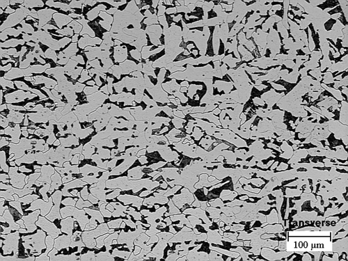 |
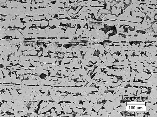
| Figure 2. An optical micrograph of steel for the hull of the Titanic in (a—top) longitudinal and (b—bottom) transverse directions, showing banding that resulted in elongated pearlite colonies and MnS particles. Etchant is 2% Nital. |
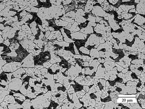 |
| Figure 3. The microstructure of ASTM A36 steel showing ferrite and pearlite. The mean grain diameter is 26.173 µm. Etchant is 2% Nital. |
 |
| Figure 4. A scanning electron micrograph of the etched surface of the Titanic hull steel showing pearlite colonies, ferrite grains, an elongated MnS particle, and nonmetallic inclusions. Etchant is 2% Nital. |
 |
| Figure 5. A scanning electron micrograph of a Charpy impact fracture surface newly created at 0°C, showing cleavage planes containing ledges and protruding MnS particles. |
 |
| Figure 6. A scanning electron micrograph showing a fractured MnS particle protruding edge-on from the fracture surface. |
During an expedition to the wreckage in the North Atlantic on August 15, 1996, researchers brought back steel from the hull of the ship for metallurgical analysis. After the steel was received at the University of Missouri-Rolla, the first step was to determine its composition. The chemical analysis of the steel from the hull is given in Table II. The first item noted is the very low nitrogen content. This indicates that the steel was not made by the Bessemer process; such steel would have a high nitrogen content that would have made it very brittle, particularly at low temperatures. In the early 20th century, the only other method for making structural steel was the open-hearth process. The fairly high oxygen and low silicon content means that the steel has only been partially deoxidized, yielding a semikilled steel. The phosphorus content is slightly higher than normal, while the sulfur content is quite high, accompanied by a low manganese content. This yielded a Mn:S ratio of 6.8:1—a very low ratio by modern standards. The presence of relatively high amounts of phosphorous, oxygen, and sulfur has a tendency to embrittle the steel at low temperatures.
Davies has shown that at the time the Titanic was constructed about two-thirds of the open-hearth steel produced in the United Kingdom was done in furnaces having acid linings. There is a high probability that the steel used in the Titanic was made in an acid-lined open-hearth furnace, which accounts for the fairly high phosphorus and high sulfur content. The lining of the basic open-hearth furnace will react with phosphorus and sulfur to help remove these two impurities from the steel. It is likely that all or most of the steel came from Glasgow, Scotland.
Included in Table II are the compositions of two other steels: steel used to construct lock gates at the Chittenden Ship Lock between Lake Washington and Puget Sound at Seattle, Washington, and the composition of a modern steel, ASTM A36. The ship lock was built around 1912, making the steel about the same age as the steel from the Titanic.
Metallography
Standard metallographic techniques were used to prepare specimens taken from the hull plate of the Titanic for optical microscopic examination. After grinding and polishing, etching was done with 2% Nital. Because earlier work by Brigham and Lafrenière showed severe banding in a specimen of the steel, specimens were cut from the hull plate in both the transverse and longitudinal directions. Figure 2 shows the microstructure of the steel. In both micrographs, it is apparent that the steel is banded, although the banding is more severe in the longitudinal section. In this section, there are large masses of MnS particles elongated in the direction of the banding. The average grain diameter is 60.40 µm for the longitudinal microstructure and 41.92 µm for the microstructure in the transverse direction. In neither micrograph can the pearlite be resolved. For comparison, Figure 3 is a micrograph of ASTM A36 steel, which has a mean grain diameter of 26.173 µm.
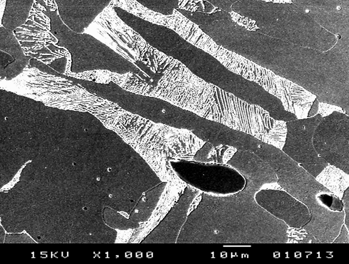
Figure 4 is a scanning electron microscopy (SEM) micrograph of the polished and etched surface of steel from the Titanic. The pearlite can be resolved in this micrograph. The dark gray areas are ferrite. The very dark elliptically shaped structure is a particle of MnS identified by energy-dispersive x-ray analysis (EDAX). It is elongated in the direction of the banding, suggesting that banding is the result of the hot rolling of the steel. There is some evidence of small nonmetallic inclusions and some of the ferrite grain boundaries are visible.
Tensile Testing
The steel plate from the hull of the Titanic was nominally 1.875 cm thick, while the bulkhead plate had a thickness of 1.25 cm. Corrosion in the salt water had reduced the thickness of the hull plate so that it was not possible to machine standard tensile specimens from it. A smaller tensile specimen with a reduced section of 0.625 cm diameter and a 2.5 cm gage length was used.
The tensile-test results are given in Table III. These data are compared with tensile-test data for an SAE 1020 steel, which is similar in composition. The steel from the Titanic has the lower yield strength, probably due to a larger grain size. The elongation increases as well, again due to a larger grain size.
Charpy Impact Tests
Charpy impact tests were performed over a range of temperatures from -55°C to 179°C on three series of standard Charpy specimens: a series of specimens machined with the specimen axis parallel to the longitudinal direction in the hull plate from the Titanic, a series machined in the transverse direction, and a series made from modern ASTM A36 steel. A Tinius Olsen model 84 universal impact tester was used to determine the impact energy to fracture for several specimens at the selected test temperatures. A chilling bath or a circulating air laboratory oven was used to prepare the specimens for testing at specific temperatures. The specimens were allowed to soak in the appropriate apparatus for at least 20 minutes at the selected temperature. Pairs of specimens were tested at identical test temperatures.
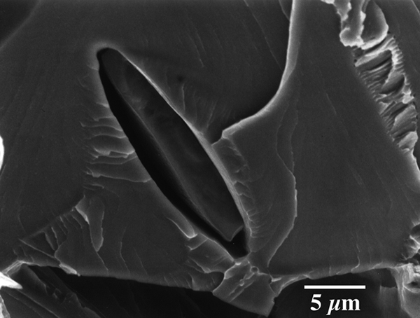
Figure 5 is an SEM micrograph of a freshly fractured surface of a longitudinal Charpy specimen tested at 0°C. The cleavage planes, (100) in ferrite, are quite apparent. There are cleavage plane surfaces at different levels that are defined by straight lines. These straight lines are steps connecting parallel cleavage planes; the edges are parallel to the [010] direction. The crystallographic surfaces of the risers are the (001) plane. In addition, there are curved slip lines on the cleavage planes.
Particles of MnS identified by EDAX can be observed. Some of the MnS particles exist as protrusions from the surface. These protrusions were pulled out of the complimentary fracture surface. In addition, there are the intrusions remaining after the MnS particles have been pulled out of this fracture surface. One of the pearlite colonies lying in the fracture surface is oriented so that the ferrite and cementite plates have been resolved. Figure 6 shows a fractured lenticular MnS particle that protrudes edge-on from the fractured surface. There are slip lines radiating away from the MnS particle.
| Table III. A Comparison of Tensile Testing of TitanicSteel and SAE 1020 | ||
|---|---|---|
| Titanic | SAE 1020 | |
| Yield Strength | 193.1 MPa | 206.9 MPa |
| Tensile Strength | 417.1 MPa | 379.2 MPa |
| Elongation | 29% | 26% |
| Reduction in Area | 57.1% | 50% |
Figure 7 is a plot of the impact energy versus temperature for the three series of specimens. At higher temperatures, the specimens prepared from the hull plate in the longitudinal direction have substantially better impact properties than for the transverse specimens. At low temperatures, the impact energy required to fracture the longitudinal and transverse specimens is essentially the same. The severe banding is certainly the cause of the differences in the impact energy to cause fracture at elevated temperatures. The specimens made from ASTM A36 steel have the best impact properties. The ductile-brittle transition temperature determined at an impact energy of 20 joules is -27°C for ASTM A36, 32°C for the longitudinal specimens made from the Titanic hull plate, and 56°C for the transverse specimens. It is apparent that the steel used for the hull was not suited for service at low temperatures. The seawater temperature at the time of the collision was -2°C.
Comparing the composition of the Titanic steel and ASTM A36 steel shows that the modern steel has a higher manganese content and lower sulfur content, yielding a higher Mn:S ratio that reduced the ductile-brittle transition temperature substantially. In addition, ASTM A36 steel has a substantially lower phosphorus content, which will also lower the ductile-brittle transition temperature. Jankovic found that the ductile-brittle transition temperature for the Chittenden lock gate steel was 33°C. The longitudinal specimens of the Titanic hull steel made in the United Kingdom and those specimens from the Chittenden lock steel made in the United States have nearly the same ductile-brittle transition temperature.
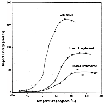 |  |
| Figure 7. Charpy impact energy versus temperature for longitudinal and transverse Titanic specimens and ASTM A36 steel. | Figure 8. Shear fracture percent from Charpy impact tests versus temperature for longitudinal and transverse Titanic specimens and ASTM A36 steel. |
Shear Fracture Percent
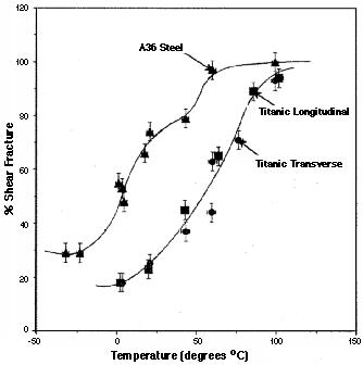
At low temperatures where the impact energy required for fracture is less, a faceted surface of cleaved planes of ferrite is observed, indicating brittle fracture. At elevated temperatures, where the energy to cause fracture is greater, a ductile fracture with a shear structure is observed. Figure 8 is a plot of the shear fracture percent versus temperature. There is a fairly strong similarity between this figure and Figure 7, which should be expected as they represent the different measurements of the same phenomenon. Using 50% shear fracture area as a reference point, this would occur in ASTM A36 at -3°C, while for the Titanic steel, this value would occur at 49°C in the longitudinal direction and at 59°C in the transverse direction. At elevated temperatures, the impact-energy values for the longitudinal Titanic steel is substantially greater than the transverse specimens, as shown in Figure 7. The difference between the longitudinal and transverse shear fracture percent from the Titanic is much smaller. This suggests that the banding is a more important factor in the results for the impact-energy experiment as compared with shear fracture percent.
CONCLUSIONS
The steel used in constructing the RMS Titanic was probably the best plain carbon ship plate available in the period of 1909 to 1911, but it would not be acceptable at the present time for any construction purposes and particularly not for ship construction. Whether a ship constructed of modern steel would have suffered as much damage as the Titanic in a similar accident seems problematic. Navigational aides exist now that did not exist in 1912; hence, icebergs would be sighted at a much greater distance, allowing more time for evasive action. If the Titanic had not collided with the iceberg, it could have had a career of more than 20 years as the Olympic had. It was built of similar steel, in the same shipyard, and from the same design. The only difference was a big iceberg.
ACKNOWLEDGEMENTS
The authors thank G. Tullock of RMS Titanic, Inc., for supplying the steel from the Titanic and W. Garzke, Jr., of Gibbs and Cox, for his assistance in securing the steel. Thanks to D. Brown and M.K. Johnson and their associates of Laclede Steel Company for the chemical analysis of the steel. S. Miller of the Electron Microscope Laboratory and associate professor C. Ramsay are thanked for their assistance. Thanks to T. Foecke of the Metallurgy Division, National Institute of Science and Technology, for providing Figure 6. Last, but certainly not least, the authors acknowledge the assistance of M. Roberson, J. Jones, G. Papen, and D. Murphy of the School of Mines and Metallurgy shop at the University of Missouri-Rolla for their valuable assistance in preparing specimens and providing technical support.
Why Did the World Trade Center Collapse? Science, Engineering, and Speculation
Thomas W. Eagar and Christopher Musso
Editor’s Note: For a more complete. updated analysis of the World Trade Center towers collapse, read “The Role of Metallurgy in the NIST Investigation of the World Trade Center Towers Collapse” in the December 2007 issue.
 |
|---|
OTHER ARTICLES IN THE WTC SERIES |
| Why Did the World Trade Center Collapse? Science, Engineering, and Speculation by Thomas Eagar and Christopher Musso Better Materials Can Reduce the Threat from Terrorism by Toni G. Maréchaux An Initial Microstructural Analysis of A36 Steel from WTC Building 7 by J.R. Barnett, R.R. Biederman, and R.D. Sisson, Jr. News & Update |
INTRODUCTION
The collapse of the World Trade Center (WTC) towers on September 11, 2001, was as sudden as it was dramatic; the complete destruction of such massive buildings shocked nearly everyone. Immediately afterward and even today, there is widespread speculation that the buildings were structurally deficient, that the steel columns melted, or that the fire suppression equipment failed to operate. In order to separate the fact from the fiction, we have attempted to quantify various details of the collapse.
The major events include the following:
The major events include the following:
- The airplane impact with damage to the columns.
- The ensuing fire with loss of steel strength and distortion (Figure 1).
- The collapse, which generally occurred inward without significant tipping (Figure 2).
Each will be discussed separately, but initially it is useful to review the overall design of the towers.
THE DESIGN
The towers were designed and built in the mid-1960s through the early 1970s. They represented a new approach to skyscrapers in that they were to be very lightweight and involved modular construction methods in order to accelerate the schedule and to reduce the costs.
To a structural engineer, a skyscraper is modeled as a large cantilever vertical column. Each tower was 64 m square, standing 411 m above street level and 21 m below grade. This produces a height-to-width ratio of 6.8. The total weight of the structure was roughly 500,000 t, but wind load, rather than the gravity load, dominated the design. The building is a huge sail that must resist a 225 km/h hurricane. It was designed to resist a wind load of 2 kPa—a total of lateral load of 5,000 t.
In order to make each tower capable of withstanding this wind load, the architects selected a lightweight “perimeter tube” design consisting of 244 exterior columns of 36 cm square steel box section on 100 cm centers (see Figure 3). This permitted windows more than one-half meter wide. Inside this outer tube there was a 27 m × 40 m core, which was designed to support the weight of the tower. It also housed the elevators, the stairwells, and the mechanical risers and utilities. Web joists 80 cm tall connected the core to the perimeter at each story. Concrete slabs were poured over these joists to form the floors. In essence, the building is an egg-crate construction that is about 95 percent air, explaining why the rubble after the collapse was only a few stories high.
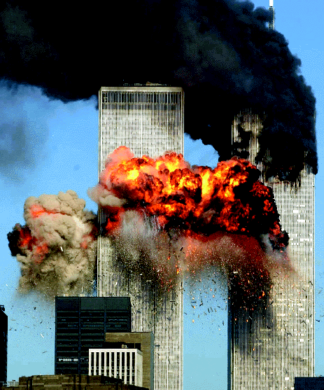 |
Figure 1. Flames and debris exploded from the World Trade Center south tower immediately after the airplane’s impact. The black smoke indicates a fuel-rich fire (Getty Images). |
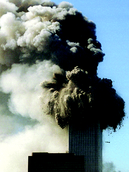 |
Figure 2. As the heat of the fire intensified, the joints on the most severely burned floors gave way, causing the perimeter wall columns to bow outward and the floors above them to fall. The buildings collapsed within ten seconds, hitting bottom with an estimated speed of 200 km/h (Getty Images). |
The egg-crate construction made a redundant structure (i.e., if one or two columns were lost, the loads would shift into adjacent columns and the building would remain standing). Prior to the World Trade Center with its lightweight perimeter tube design, most tall buildings contained huge columns on 5 m centers and contained massive amounts of masonry carrying some of the structural load. The WTC was primarily a lightweight steel structure; however, its 244 perimeter columns made it “one of the most redundant and one of the most resilient” skyscrapers.
THE AIRLINE IMPACT
The early news reports noted how well the towers withstood the initial impact of the aircraft; however, when one recognizes that the buildings had more than 1,000 times the mass of the aircraft and had been designed to resist steady wind loads of 30 times the weight of the aircraft, this ability to withstand the initial impact is hardly surprising. Furthermore, since there was no significant wind on September 11, the outer perimeter columns were only stressed before the impact to around 1/3 of their 200 MPa design allowable.
The only individual metal component of the aircraft that is comparable in strength to the box perimeter columns of the WTC is the keel beam at the bottom of the aircraft fuselage. While the aircraft impact undoubtedly destroyed several columns in the WTC perimeter wall, the number of columns lost on the initial impact was not large and the loads were shifted to remaining columns in this highly redundant structure. Of equal or even greater significance during this initial impact was the explosion when 90,000 L gallons of jet fuel, comprising nearly 1/3 of the aircraft’s weight, ignited. The ensuing fire was clearly the principal cause of the collapse (Figure 4).
The only individual metal component of the aircraft that is comparable in strength to the box perimeter columns of the WTC is the keel beam at the bottom of the aircraft fuselage. While the aircraft impact undoubtedly destroyed several columns in the WTC perimeter wall, the number of columns lost on the initial impact was not large and the loads were shifted to remaining columns in this highly redundant structure. Of equal or even greater significance during this initial impact was the explosion when 90,000 L gallons of jet fuel, comprising nearly 1/3 of the aircraft’s weight, ignited. The ensuing fire was clearly the principal cause of the collapse (Figure 4).
THE FIRE
The fire is the most misunderstood part of the WTC collapse. Even today, the media report (and many scientists believe) that the steel melted. It is argued that the jet fuel burns very hot, especially with so much fuel present. This is not true.
Part of the problem is that people (including engineers) often confuse temperature and heat. While they are related, they are not the same. Thermodynamically, the heat contained in a material is related to the temperature through the heat capacity and the density (or mass). Temperature is defined as an intensive property, meaning that it does not vary with the quantity of material, while the heat is an extensive property, which does vary with the amount of material. One way to distinguish the two is to note that if a second log is added to the fireplace, the temperature does not double; it stays roughly the same, but the size of the fire or the length of time the fire burns, or a combination of the two, doubles. Thus, the fact that there were 90,000 L of jet fuel on a few floors of the WTC does not mean that this was an unusually hot fire. The temperature of the fire at the WTC was not unusual, and it was most definitely not capable of melting steel.
In combustion science, there are three basic types of flames, namely, a jet burner, a pre-mixed flame, and a diffuse flame. A jet burner generally involves mixing the fuel and the oxidant in nearly stoichiometric proportions and igniting the mixture in a constant-volume chamber. Since the combustion products cannot expand in the constant-volume chamber, they exit the chamber as a very high velocity, fully combusted, jet. This is what occurs in a jet engine, and this is the flame type that generates the most intense heat.
In a pre-mixed flame, the same nearly stoichiometric mixture is ignited as it exits a nozzle, under constant pressure conditions. It does not attain the flame velocities of a jet burner. An oxyacetylene torch or a Bunsen burner is a pre-mixed flame.
In a diffuse flame, the fuel and the oxidant are not mixed before ignition, but flow together in an uncontrolled manner and combust when the fuel/oxidant ratios reach values within the flammable range. A fireplace flame is a diffuse flame burning in air, as was the WTC fire.
Diffuse flames generate the lowest heat intensities of the three flame types.
If the fuel and the oxidant start at ambient temperature, a maximum flame temperature can be defined. For carbon burning in pure oxygen, the maximum is 3,200°C; for hydrogen it is 2,750°C. Thus, for virtually any hydrocarbons, the maximum flame temperature, starting at ambient temperature and using pure oxygen, is approximately 3,000°C.
This maximum flame temperature is reduced by two-thirds if air is used rather than pure oxygen. The reason is that every molecule of oxygen releases the heat of formation of a molecule of carbon monoxide and a molecule of water. If pure oxygen is used, this heat only needs to heat two molecules (carbon monoxide and water), while with air, these two molecules must be heated plus four molecules of nitrogen. Thus, burning hydrocarbons in air produces only one-third the temperature increase as burning in pure oxygen because three times as many molecules must be heated when air is used. The maximum flame temperature increase for burning hydrocarbons (jet fuel) in air is, thus, about 1,000°C—hardly sufficient to melt steel at 1,500°C.
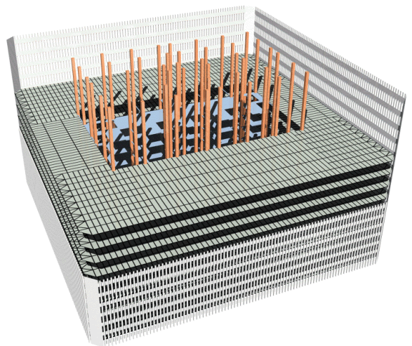 |
Figure 3. A cutaway view of WTC structure. |
 |
Figure 4. A graphic illustration, from the USA Today newspaper web site, of the World Trade Center points of impact. Click on the image above to access the actual USA Today feature. |
But it is very difficult to reach this maximum temperature with a diffuse flame. There is nothing to ensure that the fuel and air in a diffuse flame are mixed in the best ratio. Typically, diffuse flames are fuel rich, meaning that the excess fuel molecules, which are unburned, must also be heated. It is known that most diffuse fires are fuel rich because blowing on a campfire or using a blacksmith’s bellows increases the rate of combustion by adding more oxygen. This fuel-rich diffuse flame can drop the temperature by up to a factor of two again. This is why the temperatures in a residential fire are usually in the 500°C to 650°C range. It is known that the WTC fire was a fuel-rich, diffuse flame as evidenced by the copious black smoke. Soot is generated by incompletely burned fuel; hence, the WTC fire was fuel rich—hardly surprising with 90,000 L of jet fuel available. Factors such as flame volume and quantity of soot decrease the radiative heat loss in the fire, moving the temperature closer to the maximum of 1,000°C. However, it is highly unlikely that the steel at the WTC experienced temperatures above the 750–800°C range. All reports that the steel melted at 1,500°C are using imprecise terminology at best.
Some reports suggest that the aluminum from the aircraft ignited, creating very high temperatures. While it is possible to ignite aluminum under special conditions, such conditions are not commonly attained in a hydrocarbon-based diffuse flame. In addition, the flame would be white hot, like a giant sparkler. There was no evidence of such aluminum ignition, which would have been visible even through the dense soot.
It is known that structural steel begins to soften around 425°C and loses about half of its strength at 650°C. This is why steel is stress relieved in this temperature range. But even a 50% loss of strength is still insufficient, by itself, to explain the WTC collapse. It was noted above that the wind load controlled the design allowables. The WTC, on this low-wind day, was likely not stressed more than a third of the design allowable, which is roughly one-fifth of the yield strength of the steel. Even with its strength halved, the steel could still support two to three times the stresses imposed by a 650°C fire.
The additional problem was distortion of the steel in the fire. The temperature of the fire was not uniform everywhere, and the temperature on the outside of the box columns was clearly lower than on the side facing the fire. The temperature along the 18 m long joists was certainly not uniform. Given the thermal expansion of steel, a 150°C temperature difference from one location to another will produce yield-level residual stresses. This produced distortions in the slender structural steel, which resulted in buckling failures. Thus, the failure of the steel was due to two factors: loss of strength due to the temperature of the fire, and loss of structural integrity due to distortion of the steel from the non-uniform temperatures in the fire.
THE COLLAPSE
Nearly every large building has a redundant design that allows for loss of one primary structural member, such as a column. However, when multiple members fail, the shifting loads eventually overstress the adjacent members and the collapse occurs like a row of dominoes falling down.
The perimeter tube design of the WTC was highly redundant. It survived the loss of several exterior columns due to aircraft impact, but the ensuing fire led to other steel failures. Many structural engineers believe that the weak points—the limiting factors on design allowables—were the angle clips that held the floor joists between the columns on the perimeter wall and the core structure (see Figure 5). With a 700 Pa floor design allowable, each floor should have been able to support approximately 1,300 t beyond its own weight. The total weight of each tower was about 500,000 t.
As the joists on one or two of the most heavily burned floors gave way and the outer box columns began to bow outward, the floors above them also fell. The floor below (with its 1,300 t design capacity) could not support the roughly 45,000 t of ten floors (or more) above crashing down on these angle clips. This started the domino effect that caused the buildings to collapse within ten seconds, hitting bottom with an estimated speed of 200 km per hour. If it had been free fall, with no restraint, the collapse would have only taken eight seconds and would have impacted at 300 km/h. It has been suggested that it was fortunate that the WTC did not tip over onto other buildings surrounding the area. There are several points that should be made. First, the building is not solid; it is 95 percent air and, hence, can implode onto itself. Second, there is no lateral load, even the impact of a speeding aircraft, which is sufficient to move the center of gravity one hundred feet to the side such that it is not within the base footprint of the structure. Third, given the near free-fall collapse, there was insufficient time for portions to attain significant lateral velocity. To summarize all of these points, a 500,000 t structure has too much inertia to fall in any direction other than nearly straight down.
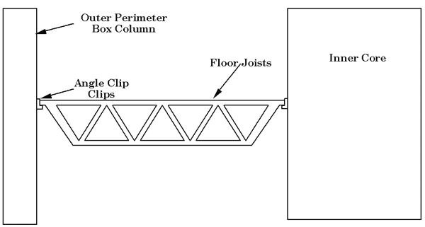 |
Figure 5. Unscaled schematic of WTC floor joints and attachment to columns. |
WAS THE WTC DEFECTIVELY DESIGNED?
The World Trade Center was not defectively designed. No designer of the WTC anticipated, nor should have anticipated, a 90,000 L Molotov cocktail on one of the building floors. Skyscrapers are designed to support themselves for three hours in a fire even if the sprinkler system fails to operate. This time should be long enough to evacuate the occupants. The WTC towers lasted for one to two hours—less than the design life, but only because the fire fuel load was so large. No normal office fires would fill 4,000 square meters of floor space in the seconds in which the WTC fire developed. Usually, the fire would take up to an hour to spread so uniformly across the width and breadth of the building. This was a very large and rapidly progressing fire (very high heat but not unusually high temperature). Further information about the design of the WTC can be found on the World Wide Web.
WHERE DO WE GO FROM HERE
The clean-up of the World Trade Center will take many months. After all, 1,000,000 t of rubble will require 20,000 to 30,000 truckloads to haul away the material. The asbestos fire insulation makes the task hazardous for those working nearby. Interestingly, the approximately 300,000 t of steel is fully recyclable and represents only one day’s production of the U.S. steel industry. Separation of the stone and concrete is a common matter for modern steel shredders. The land-filling of 700,000 t of concrete and stone rubble is more problematic. However, the volume is equivalent to six football fields, 6–9 m deep, so it is manageable.
There will undoubtedly be a number of changes in the building codes as a result of the WTC catastrophe. For example, emergency communication systems need to be upgraded to speed up the notice for evacuation and the safest paths of egress. Emergency illumination systems, separate from the normal building lighting, are already on the drawing boards as a result of lessons learned from the WTC bombing in 1993. There will certainly be better fire protection of structural members. Protection from smoke inhalation, energy-absorbing materials, and redundant means of egress will all be considered.
A basic engineering assessment of the design of the World Trade Center dispels many of the myths about its collapse. First, the perimeter tube design of the towers protected them from failing upon impact. The outer columns were engineered to stiffen the towers in heavy wind, and they protected the inner core, which held the gravity load. Removal of some of the outer columns alone could not bring the building down. Furthermore, because of the stiffness of the perimeter design, it was impossible for the aircraft impact to topple the building.
However, the building was not able to withstand the intense heat of the jet fuel fire. While it was impossible for the fuel-rich, diffuse-flame fire to burn at a temperature high enough to melt the steel, its quick ignition and intense heat caused the steel to lose at least half its strength and to deform, causing buckling or crippling. This weakening and deformation caused a few floors to fall, while the weight of the stories above them crushed the floors below, initiating a domino collapse.
It would be impractical to design buildings to withstand the fuel load induced by a burning commercial airliner. Instead of saving the building, engineers and officials should focus on saving the lives of those inside by designing better safety and evacuation systems.
As scientists and engineers, we must not succumb to speculative thinking when a tragedy such as this occurs. Quantitative reasoning can help sort fact from fiction, and can help us learn from this unfortunate disaster. As Lord Kelvin said,
“I often say . . . that when you can measure what you are speaking about, and express it in numbers, you know something about it; but when you cannot measure it, when you cannot express it in numbers, your knowledge is of a meager and unsatisfactory kind; it may be the beginning of knowledge, but you have scarcely, in your thoughts, advanced to the stage of science, whatever the matter may be.”
We will move forward from the WTC tragedy and we will engineer better and safer buildings in the future based, in part, on the lessons learned at the WTC. The reason the WTC collapse stirs our emotions so deeply is because it was an intentional attack on innocent people. It is easier to accept natural or unintentional tragedies; it is the intentional loss of life that makes us fear that some people have lost their humanity.
Copyright held by The Minerals, Metals & Materials Society, 2001
Subscribe to:
Posts (Atom)